
Create Your First Perforated Pattern in Mesh Editor
This quickstart uses HoleSnap Mesh Editor to create a simple circle grid on a 300 × 200 mm canvas and export it as a DXF file. It is the shortest complete workflow for learning where the core controls are and how to recognize a successful result.
Before You Start
- Open the current Mesh Editor at
/apps/mesh. - Use the English interface while following this version of the guide.
- Sign in before the export step. Building and previewing the pattern does not require project save access, but export requires an account.
- Use the example values as a learning setup, not as manufacturing recommendations.
What You Will Make
The result is a rectangular 300 × 200 mm design area filled with evenly spaced circular openings. The example uses Circle, a Circle Radius of 8 mm, and a Square Grid with a 20 mm gap.
Steps
- Open the Canvas panel. Set Width to
300mm and Height to200mm. The canvas changes to a 3:2 rectangle.
- Open the Shape Style panel. Choose Circle and set Circle Radius to
8mm. The preview should still show circular instances after the value changes.
- Open the Layout Mode panel. Select Regular, choose Grid, and keep Grid Type set to Square.
- Set H Gap to
20mm. Square Grid keeps the vertical spacing equal to the horizontal spacing, so a separate V Gap control is not shown.
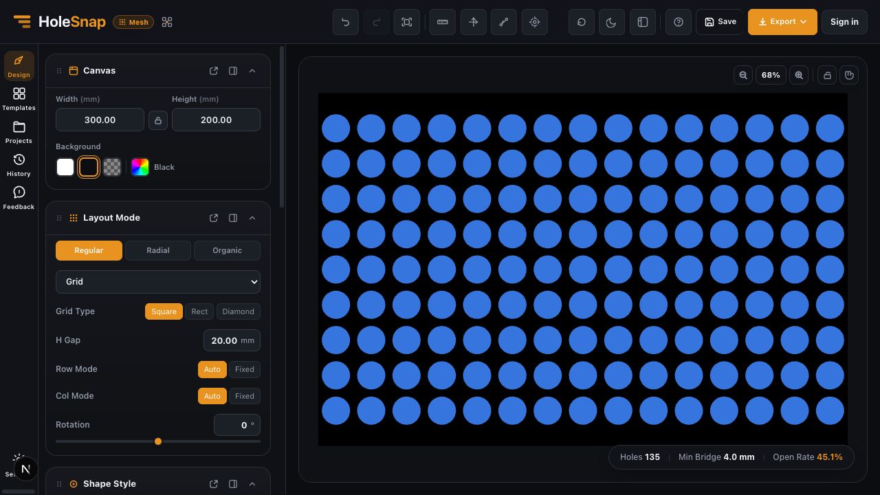
- Read the status area. Confirm that Holes, Open Rate, and Min Bridge all display values. In the current build used for this guide, the example produces 135 holes, a 45.1% open rate, and a 4.0 mm minimum bridge.
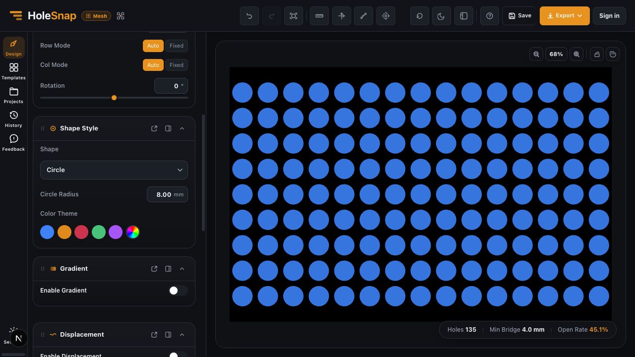
- Inspect all four edges of the preview. If the design does not need a separate board outline or trimmed edge geometry, leave Boundary unchanged for this first exercise.
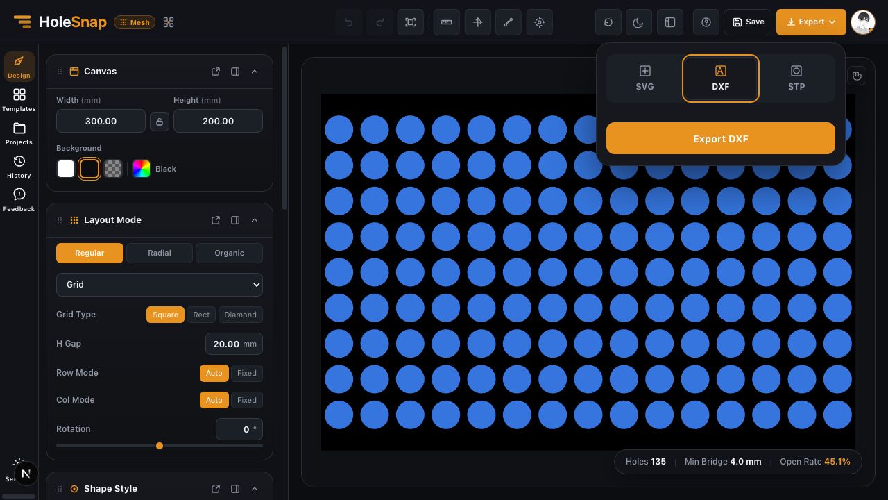
- Sign in, open Export, and choose DXF. In a fresh editor, the DXF defaults use millimeters and include the board outline; the current compact export panel does not show separate DXF configuration controls.
- Select Export DXF and wait for the file to complete. Large jobs may be queued, but this basic grid remains well below the DXF hole limit.
Check the Result
Open the DXF in the CAD/CAM software you plan to use. Confirm:
- The overall design measures 300 × 200 mm.
- The openings are circles arranged in aligned rows and columns.
- The board outline is present or absent as intended.
- There are no unexpected duplicate contours.
- The edge treatment and minimum bridge are appropriate for the intended process.
The task is complete when the downstream software shows the expected dimensions and geometry. A successful download alone does not confirm fabrication readiness.
If the Result Looks Wrong
- The pattern is too dense: Increase H Gap, or reduce Circle Radius.
- The pattern is too sparse: Reduce H Gap gradually and watch Min Bridge.
- The canvas changed proportion unexpectedly: Check whether the Canvas aspect-ratio lock is enabled.
- Export asks you to sign in: Authentication is required for Mesh Editor export.
- The exported scale is wrong: A fresh editor defaults to millimeters, but the compact export panel does not expose a unit selector. Check the import units in the target software and confirm the 300 × 200 mm result.
Related Guides
- Editor Workspace Overview
- How to Set Panel Size in Millimeters
- Choose a Hole Shape for Your Perforated Panel
- Check a Pattern Before Export