
Choose a Hole Shape for Your Perforated Panel
The Shape Style panel controls the geometry repeated by the active Layout. Choose a shape based on the result you need, then check spacing and minimum bridge again because every shape changes the occupied area differently.
Available Shapes
Mesh Editor currently provides:
- Circle
- Rectangle
- Polygon
- Diamond
- Star
- Ring
- Custom Shape
“Slot” is not a separate Shape option. Create a slot-like opening with Rectangle, an elongated width-to-height ratio, and Corner Radius.
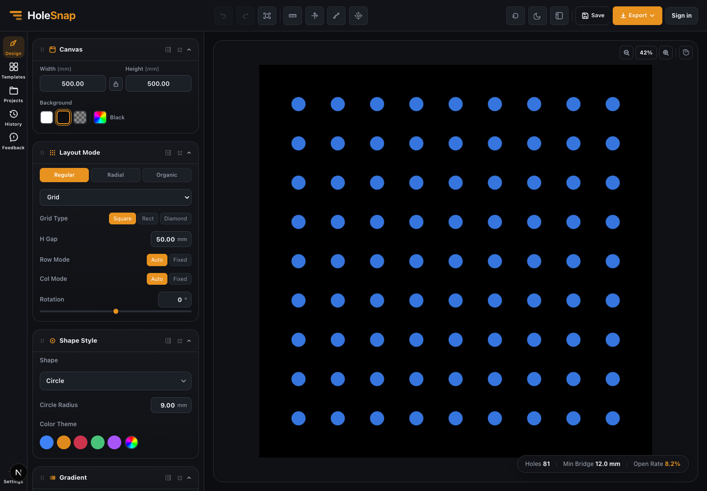
Common Choices
Circle
Circle uses Circle Radius. It is the clearest starting point for learning spacing, open rate, and minimum bridge behavior.
Rectangle and Slot-Like Shapes
Rectangle exposes width and height controls. Unlock the ratio when the two dimensions should change independently, then use Corner Radius to soften the ends.
Polygon and Diamond
Polygon supports a side count, and Diamond provides a directional geometric opening. Rotation and corner settings can change the required spacing around both shapes.
Star and Ring
Star and Ring add internal or pointed geometry. Inspect the exported contours carefully because these shapes can increase file complexity and create narrow local bridges.
Custom Shape
Custom Shape opens the Path Editor for drawing or importing editable path geometry. Do not assume every SVG or DXF feature is supported; verify complex paths in the current interface and in the exported result.
Color and Export
Color Theme is mainly a preview aid. Manufacturing workflows should rely on the exported geometry and the downstream application’s layer or entity handling, not the preview color.
Check the Result
After changing Shape:
- Inspect the full outline, especially rotated corners and inner Ring geometry.
- Recheck Holes, Min Bridge, and Open Rate.
- Check edge openings when Boundary uses Trim.
- Export a small test and inspect closed contours in the target software.
Related Guides
- Layout Settings Overview
- Create a Grid Pattern in Mesh Editor
- Canvas and Preview