This workflow creates a simple perforated panel that can be exported for CAD/CAM use. It is the recommended first tutorial for new users.
 #
#
Goal #
Create a rectangular panel with a regular hole pattern and export it as a DXF file.
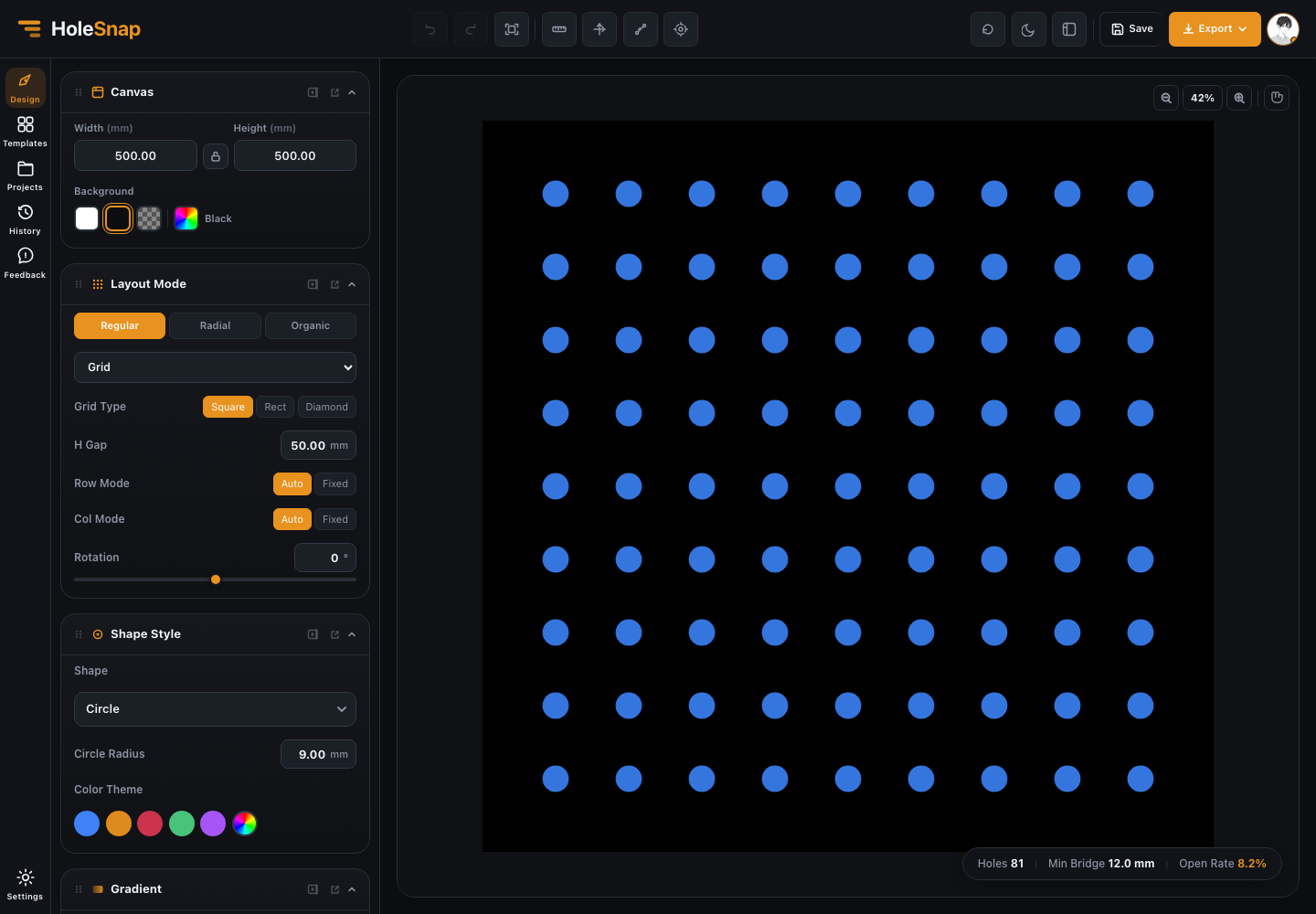
Step 1: Set the Panel Size #
Open the Canvas panel and enter the panel width and height.
Example:
- Width: 500 mm
- Height: 300 mm
If you need to keep the same proportion while resizing, turn on the aspect lock. Choose a background color that makes the holes easy to see.
Step 2: Choose the Hole Shape #
Open the Shape panel and choose a hole type.
For a first design, choose round holes. They are easy to inspect, common in manufacturing, and useful for checking open area and bridge width.
Then set the hole size. If your hole is too large for the spacing, the bridge width will become small. If the hole is too small, the open area may be lower than expected.
Step 3: Choose the Layout #
Open the Layout panel and select a regular layout.
Good first choices:
- Grid: simple rows and columns.
- Staggered: common perforated sheet look with better visual density.
- Hex-style arrangement: useful for efficient packing and airflow.
Adjust spacing or count until the pattern fills the panel cleanly.
Step 4: Watch the Status Bar #
As you change size and spacing, check:
- Hole count: more holes usually means larger files and more fabrication work.
- Open area: higher open area usually means more airflow or visibility, but less material.
- Minimum bridge: smaller bridges may be weaker or harder to fabricate.
If minimum bridge is too small, reduce hole size or increase spacing.
Step 5: Inspect the Edges #
Zoom in and check the panel edges.
Look for:
- Holes too close to the edge.
- Partial holes that may not be desired.
- Uneven spacing near boundaries.
- Areas where holes overlap or look too dense.
If needed, use the Boundary panel to trim or hide holes.
Step 6: Add a Boundary Only If Needed #
For a plain rectangle, you may not need a separate boundary. If the design should follow a circle, rounded rectangle, or imported outline, open the Boundary panel.
Use Hide when you want only complete holes inside the boundary.
Use Trim when you want the boundary to cut through holes at the edge.
Step 7: Export #
Click Export in the top bar and choose the file type.
For most fabrication workflows, start with DXF. Confirm the units before downloading.
Use SVG when you need a lightweight vector file for editing or preview.
Use STP/STEP when the receiving workflow needs a 3D CAD model.
The export panel lets you choose SVG, DXF, or STP/STEP. Start with the format your downstream tool expects, then confirm the file in CAD/CAM software before fabrication.
Step 8: Verify Outside HoleSnap #
Open the exported file in your CAD/CAM software.
Check:
- File scale
- Units
- Board outline
- Hole shape
- Edge trimming
- Minimum bridge
- Layer or object structure
Do this before sending the file to a fabricator.
Recommended Starting Values #
If you are only testing the editor, try:
- Canvas: 500 mm x 300 mm
- Shape: round
- Hole size: 8 mm
- Layout: regular or staggered
- Spacing: 16-20 mm
- Boundary: none or rectangular
- Export: DXF
These values are only a starting point. Final dimensions should match your material and manufacturing process.


