
How to Set Panel Size in Millimeters
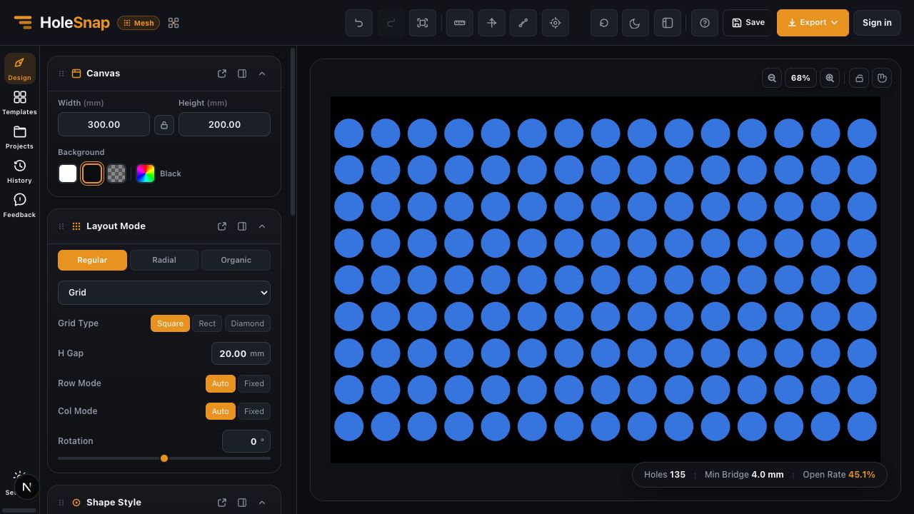
Set the Mesh Editor Canvas to the real width and height of the design before adjusting shapes, spacing, or gradients. This example creates a 300 × 200 mm design area.
Steps
- Open the Canvas panel in the Design workspace.
- Enter
300in Width and200in Height. - Leave the aspect-ratio lock off when you need to enter both dimensions independently.
- Turn the lock on only when later changes should preserve the current 3:2 ratio.
- Choose a Background that makes the openings easy to inspect. Background color does not change the geometry by itself.
Check the Result
The preview should become a 3:2 rectangle. Use Fit to View if the panel appears cropped after resizing.
Do not judge physical size from the number of screen pixels. Width and Height are the design dimensions; zoom percentage is only a viewing setting.
Continue the Design
After the Canvas is correct:
- Choose a Shape and its dimensions.
- Choose a Layout and spacing.
- Inspect Holes, Min Bridge, and Open Rate.
- Add Gradient, Effects, or Boundary only after the base pattern is understandable.
Verify After Export
Measure the exported geometry in the target CAD/CAM software. For this example, the expected overall size is 300 × 200 mm. If the imported size differs, check the receiving application’s unit settings before changing the HoleSnap Canvas.
Troubleshooting
- Both dimensions change together: Turn off the Canvas aspect-ratio lock.
- The panel seems cut off: Use Fit to View instead of increasing Width or Height.
- The exported scale is wrong: Confirm the import units in the target software.
- Edge openings change after resizing: Review the Layout fit and Boundary settings after the new Canvas size is applied.
Related Guides
- Canvas and Preview
- Choose a Hole Shape for Your Perforated Panel
- Create a Grid Pattern in Mesh Editor