
Shared-edge Grid Generator: Build Honeycomb and Geometric Vector Networks
Build continuous honeycomb, square, triangle, and diamond networks with the new Shared-edge Grid generator in HoleSnap Flow Scene, then export SVG or DXF.
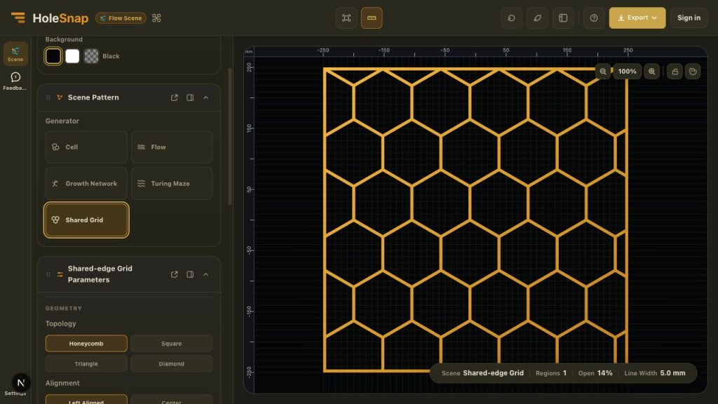
HoleSnap Flow Scene now includes Shared-edge Grid, a generator for continuous geometric networks built from cells that share the same boundaries.
This is different from placing separate holes in a repeated array. Shared-edge Grid constructs the material lines between neighboring openings as one connected network, making it a useful starting point for honeycomb grilles, geometric screens, panel concepts, and fabrication-oriented vector studies.
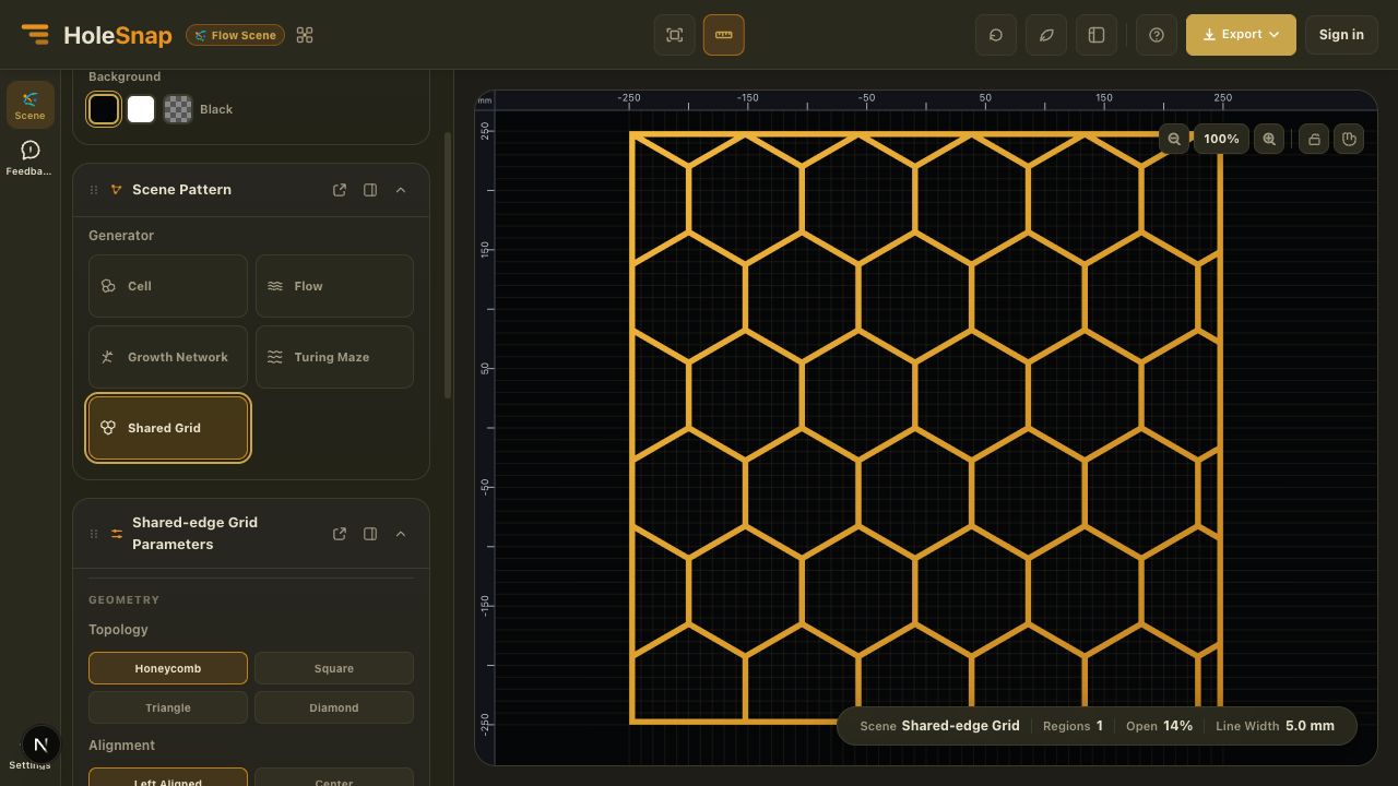
Four grid topologies
The current generator provides four topologies:
- Honeycomb creates a hexagonal network with Pointy or Flat orientation.
- Square creates an orthogonal grid that can be stretched independently in the horizontal and vertical directions.
- Triangle creates a repeated triangular network for denser directional geometry.
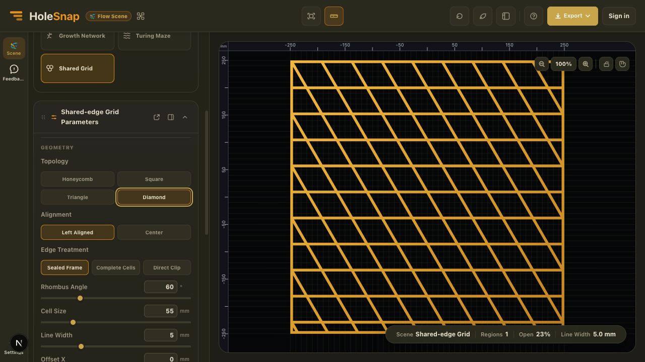
- Diamond creates an angled rhombus grid with an adjustable Rhombus Angle.
All four topologies use the same core controls for cell size, line width, alignment, offset, and scale. This makes it easy to compare different structures without rebuilding the canvas or boundary.
Choose how the grid meets the edge
Boundary treatment is especially important for a shared-edge network. The generator provides three edge treatments for different design intentions.
- Sealed Frame adds a continuous outer frame and merges the clipped network lines into it. This is the default option and avoids loose line ends at the canvas edge.
- Complete Cells keeps only openings that remain complete inside the canvas. It removes partial edge cells and does not add the sealed outer frame.
- Direct Clip cuts the network directly at the canvas boundary, preserving partial cells along the edge.
Sealed Frame is usually the clearest starting point for a closed panel concept. Complete Cells is useful when consistent cell shapes matter more than filling every edge. Direct Clip is appropriate when the grid will be combined with other geometry or finished later in CAD.
Adjust the network geometry
Use Cell Size to control the scale of the openings and Line Width to control the generated network material. Offset X and Offset Y move the lattice relative to the canvas, while Scale X and Scale Y stretch the topology without changing to another grid family.
You can also choose Left Aligned or Center alignment. Honeycomb adds Pointy and Flat orientation options, while Diamond adds a Rhombus Angle control from narrow slants to broader diamond forms.
A practical workflow
- Open HoleSnap Flow Scene.
- Set the canvas dimensions and background.
- Select Shared Grid in the Scene Pattern panel.
- Choose Honeycomb, Square, Triangle, or Diamond.
- Select an alignment and edge treatment.
- Adjust Cell Size and Line Width, then refine Offset and Scale as needed.
- For Honeycomb, choose Pointy or Flat orientation. For Diamond, adjust the Rhombus Angle.
- Review the actual open-area value in the status bar, then sign in to export SVG or DXF.
Where shared-edge grids help
Shared-edge networks are useful for ventilation grilles, speaker and fan covers, decorative screens, lightweight panel concepts, architectural pattern studies, packaging structures, product surfaces, and laser-cut prototypes.
The topology can give the design an organized rhythm while keeping the generated material network connected. Honeycomb provides a familiar technical appearance, while triangle and diamond grids create stronger directional movement.
Check the exported geometry before fabrication
Shared-edge Grid generates vector pattern geometry, not a production-approved part. The Line Width control defines the generated network geometry, but it does not account for kerf, tool diameter, material behavior, minimum feature rules, or structural loads.
Before cutting or machining, open the SVG or DXF in the software used by your fabricator. Check dimensions, units, contours, edge treatment, narrow intersections, minimum material width, and machine compatibility. Complex boundary or downstream boolean operations should also be reviewed before production.