
Create Fan Grill DXF with Polar Array
Use HoleSnap's Plus Polar Array layout to create radial fan grill DXF patterns with rings, sectors, center clearance, and adjustable spacing.
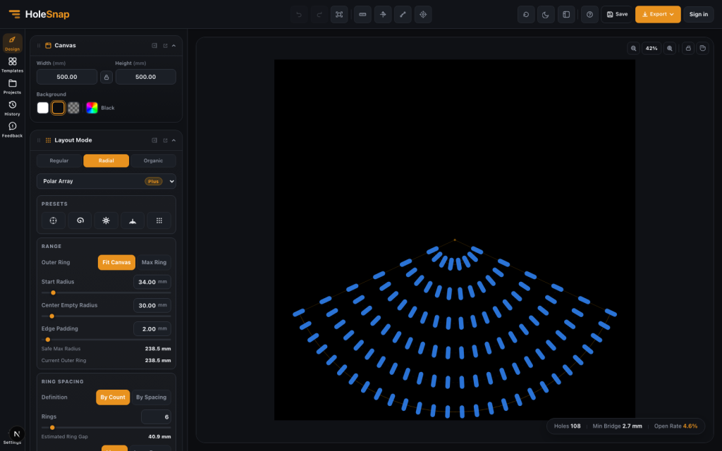
A fan grill is a good example of a design that looks simple but has several constraints. It needs airflow, protection, enough material around the openings, space for the fan hub, and a layout that fits the enclosure.
With HoleSnap’s Plus Polar Array layout, you can create the radial perforation pattern for a fan grill directly in the browser and export SVG, DXF, or STP files for laser cutting preparation, CNC planning, CAD review, or product prototyping.
This workflow creates the repeated vent pattern. It does not automatically create the finished part’s mounting holes, fastening details, or enclosure-specific outer contour. Add and verify those features in CAD before fabrication.
This article focuses on fan-specific decisions. For a control-by-control explanation of rings, presets, sectors, and orientation, read the Polar Array Pattern Generator guide.
Instead of drawing circular arrays manually in CAD, you can control the fan grill structure through parameters: ring count, radius, angle range, point distribution, center clearance, shape orientation, and export format.
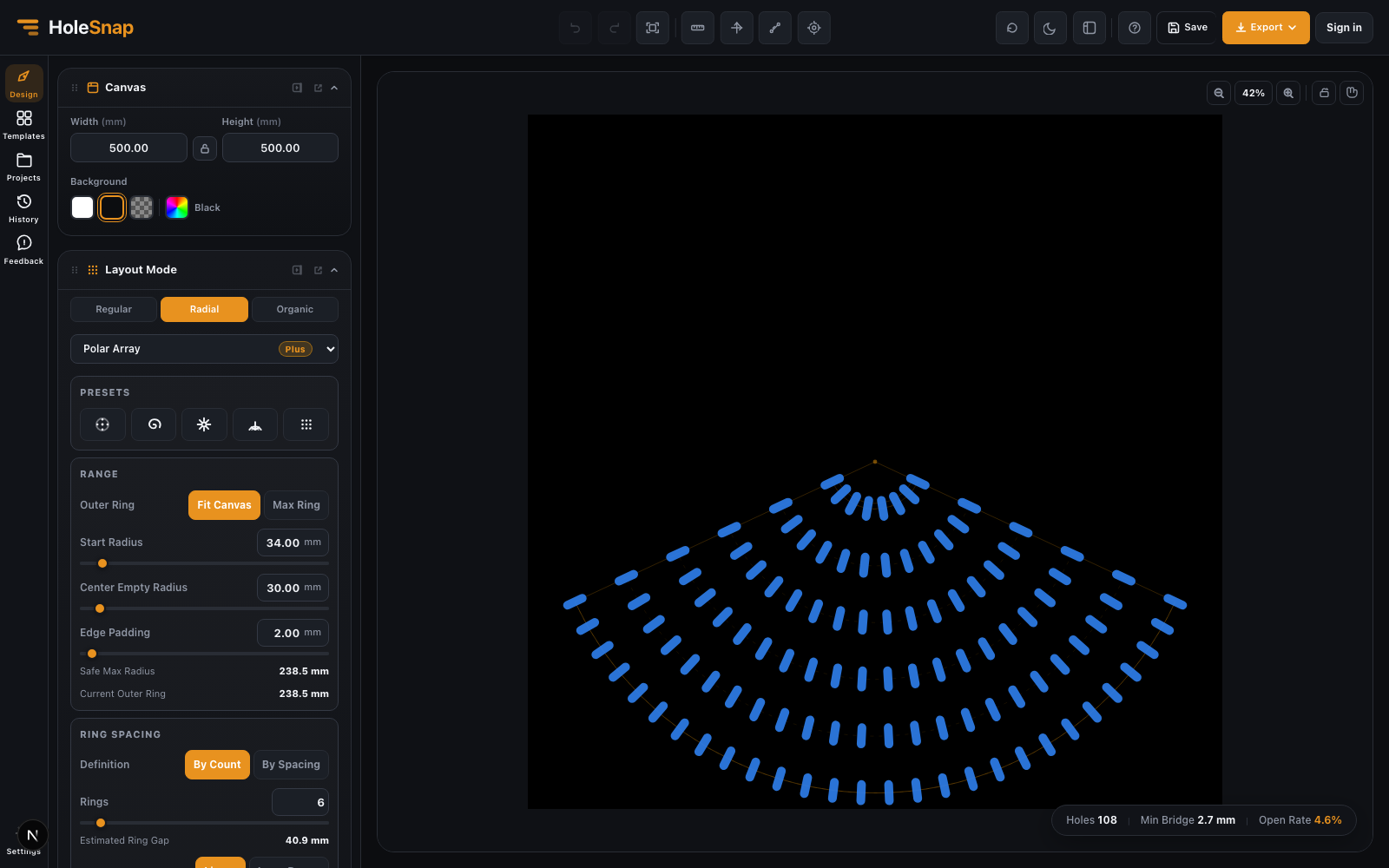
Why Use Polar Array for Fan Grills?
Most fan grills are circular or partially circular. A regular grid can work for flat ventilation areas, but it does not naturally follow the shape of a fan.
Polar Array is better suited for fan grill DXF design because it is built around radius and angle. That makes it easier to create:
- Circular rings of openings
- Radial slots
- Sector-based vents
- Tangential airflow patterns
- Center clearance for the fan hub
- Outer spacing that follows the fan boundary
This is especially useful for electronics enclosures, PC builds, 3D printer upgrades, machine guards, speaker-style covers, and small-batch product prototypes.
Step 1: Start with the Fan Size
Before choosing the visual pattern, start with the physical fan size. Common fan sizes include 40 mm, 60 mm, 80 mm, 92 mm, 120 mm, and 140 mm, but the exact values depend on your enclosure and hardware.
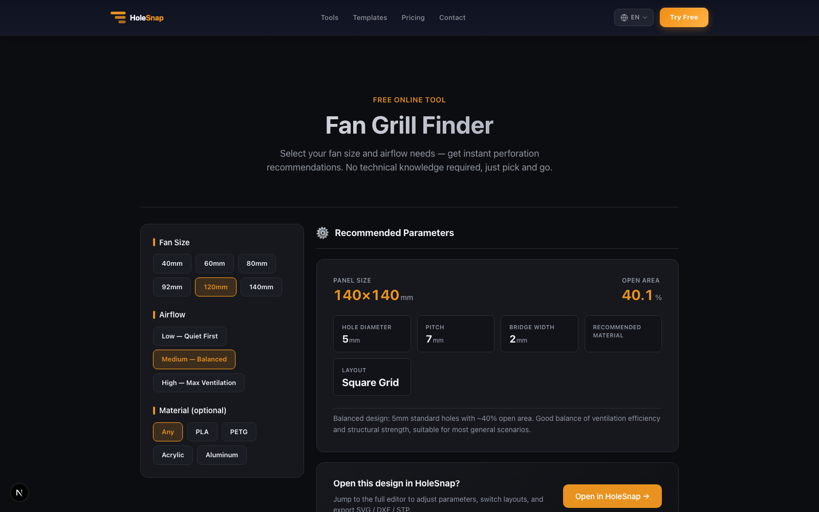
If you only need a recommended starting point, check the Fan Grill Finder first. It suggests panel size, open area, hole diameter, pitch, bridge width, and layout for common fan sizes. For a custom pattern, carry those dimensions into the HoleSnap editor.
Set the editor canvas or panel size large enough to cover the fan opening and surrounding material. If the grill is part of a rectangular front panel, use the full panel size. If the grill is a circular insert, use a square working area that matches the part.
Also note the dimensions you will need when the pattern is completed in CAD:
- Fan outer size
- Screw hole locations
- Hub diameter
- Blade clearance
- Enclosure edge margin
- Material thickness
These values affect how dense the grill can be and how close the openings should sit near the center and edge.
Step 2: Choose Polar Array
Open the HoleSnap editor, open Layout Mode, select Radial, and choose Polar Array. This changes the pattern from rows and columns to rings and angles.
For fan grill work, Polar Array gives you direct control over the circular structure. You can decide how many rings to generate, where the first ring starts, how many openings appear on each ring, and whether the layout uses a full circle or a partial sector.
If you are creating a simple fan cover, start with round openings. For a directional slot-like shape, choose Rectangle, make it elongated, increase Corner Radius, and then adjust its Polar Array orientation.
Step 3: Set Center Clearance
Most fan grills should leave space in the center. The center area may need to clear the fan hub, motor, bearing, logo badge, screw head, or structural support.
In the Polar Array Range section, use Center Empty Radius to keep the middle area open. This prevents small openings from crowding the hub region and gives the grill a cleaner structure. Use Edge Padding to preserve material near the outer edge.
A common mistake is making the center too dense. It may look interesting on screen, but it can interfere with the fan hub or create weak material bridges. Keep the center simple unless the grill is purely decorative.
Step 4: Adjust Rings and Point Distribution
The outer rings of a fan grill usually need more openings than the inner rings. This keeps the pattern visually balanced and supports airflow near the blade area.
Use Ring Spacing and Ring Points to control the structure:
- Choose By Count and increase Rings for a denser grill, or choose By Spacing and set Ring Gap.
- Choose By Radius or By Spacing under Ring Points to increase point count toward the outside.
- Reduce point count if the minimum bridge becomes too narrow.
- Choose Sequence when you need exact point counts for each ring.
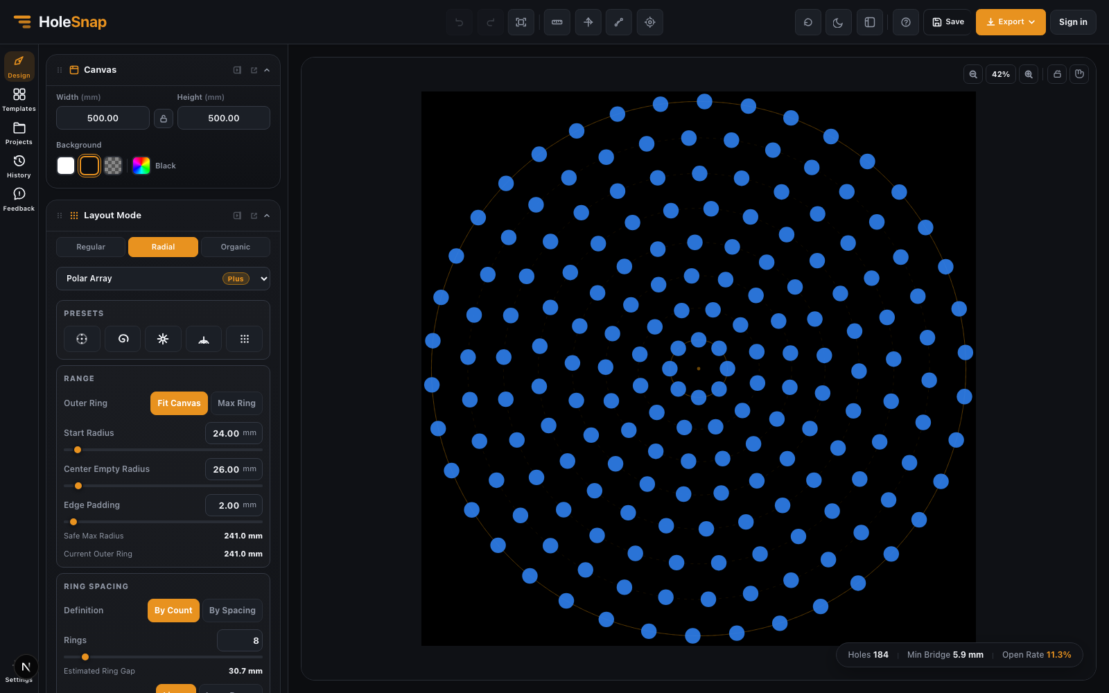
For example, a small fan cover might use fewer rings and larger bridges. A larger 120 mm fan cover can support more rings and more openings, but still needs enough material around screw holes and the outer edge.
Step 5: Use Sector Mode for Directional Fan Covers
Not every fan grill needs to be a full circular pattern. Sector mode lets you limit the pattern to part of a circle.
This is useful when:
- The enclosure only exposes part of the fan.
- The fan opening is integrated into a larger product surface.
- You want a decorative radial arc.
- The airflow pattern should have a directional look.
- You need to leave space for labels, buttons, ports, or screws.
In HoleSnap, set Range to Sector, then set Start Angle and End Angle in Angle & Twist. Use Orientation to control how the shapes face.
Tangent orientation can make slots follow the circular airflow direction. Radial orientation can make openings point outward from the center. None keeps the shape rotation fixed.
Step 6: Check Bridge Width and Open Area
A fan grill needs enough open area for airflow, but too much open area can weaken the part. The editor calls this live estimate Open Rate; compare it with your geometric open-area target rather than treating it as a measured airflow value. Minimum Bridge is also an estimate, not a material-strength guarantee.
Before exporting, check:
- Minimum bridge width between openings
- Material around the center hub
- Material around screw holes
- Outer edge margin
- Open Rate percentage
- Shape overlap
- Very small details that may not cut cleanly
For laser cutting, narrow bridges can overheat or deform. For CNC routing, slots and internal corners must respect the cutter size. For 3D printing, ribs need to be thick enough to print reliably.
Step 7: Export the Pattern and Complete the Part in CAD
When the fan grill layout is ready, export the perforation pattern as DXF for laser cutting, CNC, or CAD/CAM review.
You can also export SVG if the pattern needs more graphic editing, or STP if the design needs to move into a 3D CAD workflow.
In CAD, add the actual mounting holes and the required outer contour, then position the perforation pattern around those fixed features. Center Empty Radius reserves an unperforated region; it does not create a center cutout by itself.
After export, open the file in your CAD/CAM software and confirm:
- Units are correct.
- Scale matches the fan size.
- Contours are clean.
- No duplicate lines exist.
- Added screw holes, outer contour, and center clearance match the hardware.
- Bridges and edge margins are suitable for the material.
Practical Starting Values
There is no single correct fan grill pattern, but these starting values are useful:
- Use a center clearance slightly larger than the fan hub.
- Keep outer edge margin large enough for strength.
- Increase point count gradually toward outer rings.
- Use larger bridges for thin materials.
- Avoid tiny decorative cuts near screw holes.
- Test the exported DXF at real scale before production.
If the grill will be visible on a final product, make the pattern feel intentional. A radial fan grill can become part of the product design language, not just a cooling feature.
Final Thoughts
Polar Array makes fan grill DXF design faster because the layout matches the geometry of the part. You can build circular rings, sector vents, radial slots, and center clearances without manually rotating and copying geometry in CAD. Always verify the resulting file in your target CAD/CAM workflow before fabrication.
For makers and product designers, this turns the perforation stage into a parameter-based workflow: set the fan size, choose the pattern, compare Open Rate and Minimum Bridge estimates, export the vector pattern, and complete the hardware geometry in CAD.