A perforated halftone panel uses many holes to recreate an image. Larger holes represent one tone, smaller holes represent another, and the full panel becomes readable from a distance. This technique is useful for signage, facade studies, decorative screens, acoustic panels, and laser-cut artwork.
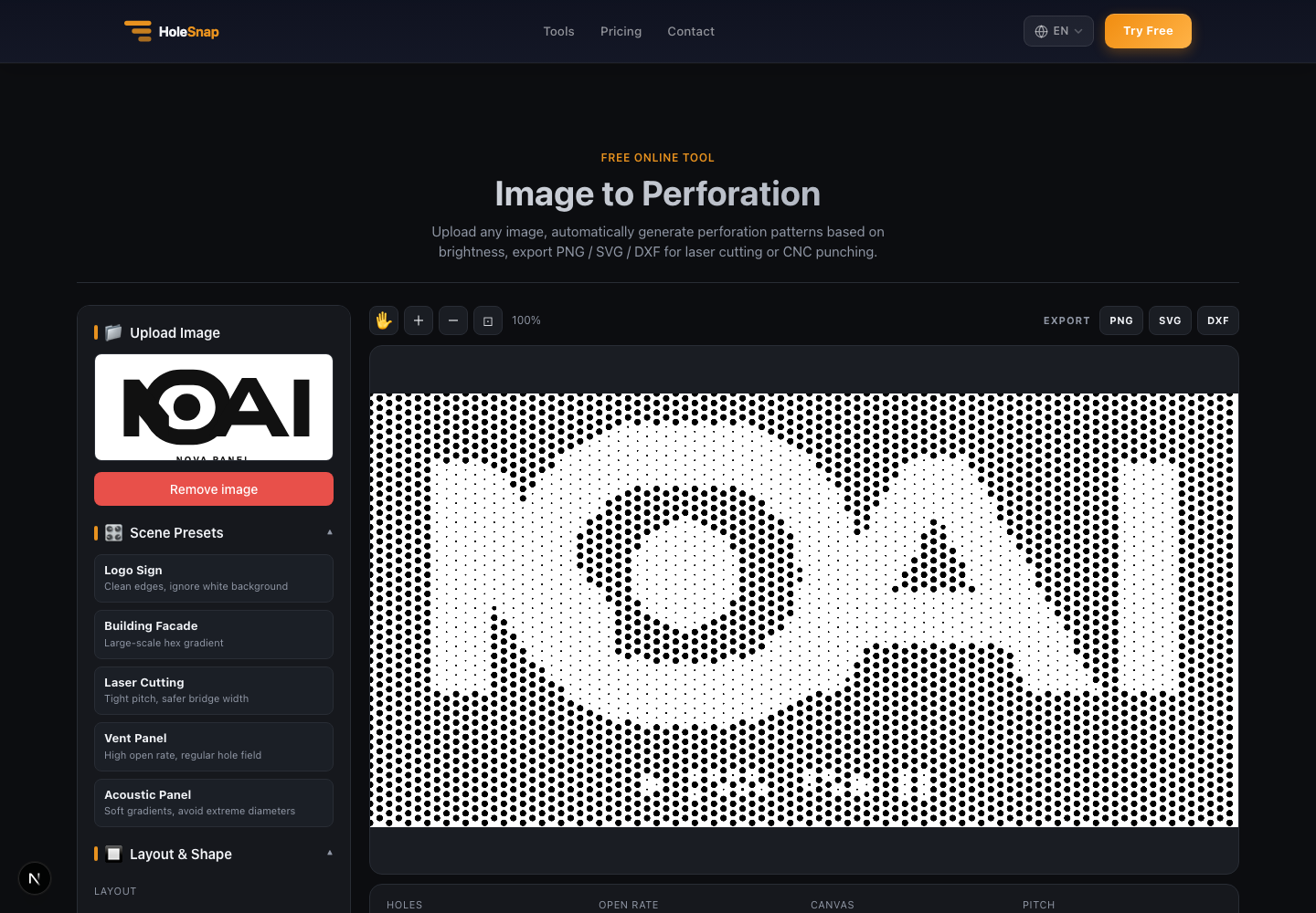
With HoleSnap’s Image to Perforation tool, you can create this effect online. Upload an image, adjust the pitch and diameter range, choose a layout, then export the result as SVG or DXF.
Why Convert an Image to DXF?
DXF is a common format for fabrication workflows. Laser cutters, CNC software, CAD programs, and many sheet-metal workflows can read DXF files.
When an image is converted into a perforated DXF pattern, it becomes editable vector geometry instead of a bitmap. That means the file can be checked, scaled, layered, nested, or prepared for toolpaths in CAD/CAM software.
Common use cases include:
- Laser-cut logo panels
- Perforated portraits or artwork
- Decorative ventilation covers
- Architectural facade mockups
- Product enclosure graphics
- Acoustic panels with visual texture
- Maker projects that need custom cut patterns
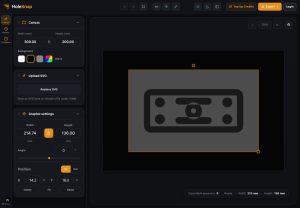
Step 1: Upload the Image
Start with an image that has a clear subject. Logos and icons are easiest. Photos can work, but high-detail photos often need more tuning.
After upload, the tool generates a perforation preview and shows the original image in the sidebar. The preview updates as you change layout, shape, pitch, diameter, contrast, gamma, and threshold.
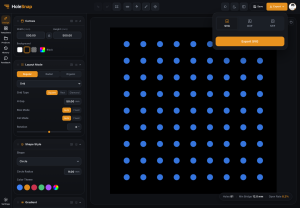
Step 2: Pick the Right Layout
Layout controls where the holes are placed.
A square grid is easy to inspect and works well for clean technical patterns. A hex or honeycomb layout can create a denser and more organic halftone feel. Staggered and triangular layouts can improve visual continuity for some images.
If the panel will be fabricated, choose a layout that leaves enough material between holes. A visually smooth halftone may not be manufacturable if pitch is too tight or maximum hole size is too large.
Step 3: Tune Pitch, Diameter, and Contrast
Pitch controls the spacing between holes. It has a major effect on both image quality and file size.
Small pitch creates more holes and more detail. Large pitch creates fewer holes and a simpler file. A very dense pattern may look good in the preview but create a heavy DXF file or a long cutting job.
Diameter settings control the tonal range:
- Minimum diameter controls the smallest visible holes.
- Maximum diameter controls the largest holes.
- A wider range increases contrast.
- A narrower range creates a softer image.
Contrast and gamma help recover detail from the source image. Threshold can simplify a design into stronger black-and-white regions. Background ignore is useful for logos or artwork on a white background.
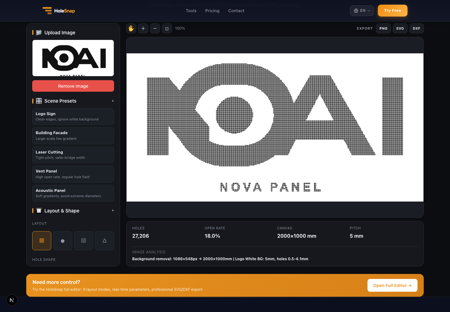
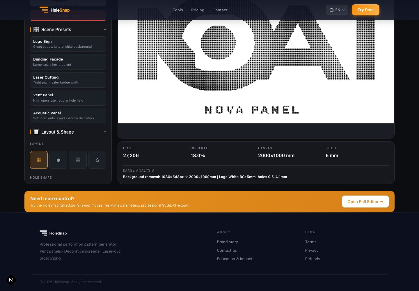
Step 4: Check Hole Count and Open Rate
The stats bar shows practical output values:
- Hole count
- Open rate
- Canvas size
- Pitch
- Image analysis recommendation
These values matter because a perforated image can easily produce tens of thousands of holes. That may be fine for a visual study, but it can be too heavy for some CAD/CAM workflows or too slow for fabrication.
If the hole count is too high, increase pitch, reduce canvas size, or simplify the image with threshold and contrast controls.
Step 5: Export SVG or DXF
Use PNG for a fast preview, SVG for vector editing, and DXF for fabrication-oriented workflows.
Before laser cutting or CNC work, open the exported DXF and check:
- Scale and units
- Hole count
- Closed paths
- Duplicate lines
- Minimum bridge width
- Edge distance
- File size
- Toolpath behavior
The online tool creates the pattern quickly, but production checks are still important.
Practical Tips for Better Image-to-DXF Results
Use simple images when possible. A high-contrast logo usually converts better than a low-contrast photo.
Think about viewing distance. A halftone panel may look sparse up close but read clearly from several meters away.
Do not chase maximum detail immediately. Start with a moderate pitch, then reduce pitch only if the file remains manageable.
Use invert brightness when the first result feels backward. Depending on the image and material, you may want dark areas to become larger holes or smaller holes.
For laser cutting, favor safer bridge widths. For facade studies, focus on large-scale visual readability. For acoustic or ventilation panels, compare open rate and airflow needs.
Final Thoughts
Image-to-DXF perforation is a powerful workflow for turning visual artwork into manufacturable patterns. It bridges the gap between bitmap images and CAD-ready vector geometry.
HoleSnap’s Image to Perforation tool lets you upload an image, generate a perforated halftone preview, tune fabrication-related parameters, and export the result as SVG or DXF. It is a fast way to explore logo panels, decorative screens, ventilation covers, and image-based laser-cut designs before committing to a final CAD file.