
What Is a Vector Pattern Generator?
Learn what a vector pattern generator is, how it supports design and fabrication workflows, and what to check before exporting SVG, DXF, or STP files.
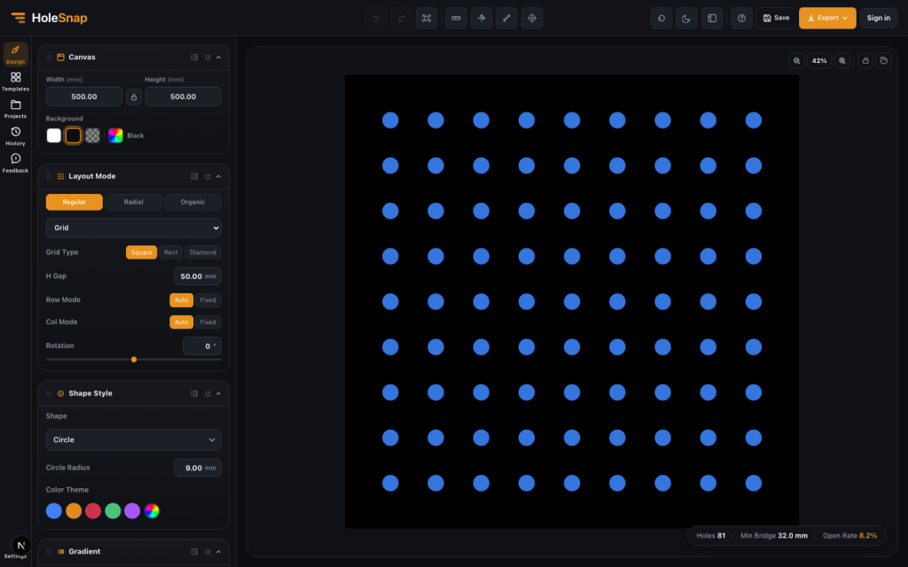
A vector pattern generator is a tool for creating repeatable geometric patterns as editable vector geometry. Instead of drawing every hole, slot, hexagon, ring, or radial element manually, you define the rules and let the generator build the pattern.
For design and fabrication workflows, this is useful because the output is not just a preview image. The pattern can be exported as SVG, DXF, or STP and passed to downstream tools for CAD review, prototyping, laser cutting preparation, CNC planning, panel design, and visual design.
HoleSnap is a vector pattern generator built around this workflow. You can create, adjust, and preview patterns in the browser; control shape, spacing, density, angle, and layout; monitor estimated open area and minimum bridge width; then export vector files for the next step.
Why Vector Patterns Matter
Many fabrication projects are pattern-based:
- Ventilation panels
- Speaker grilles
- Fan guards
- Decorative screens
- Electronics enclosure vents
- Product front panels
- Laser-cut inserts
- CNC router templates
- Perforated sheet prototypes
These designs are usually made from repeated geometry. A simple grid might use round holes. A decorative screen might use hexagons or diamonds. A fan guard might need a radial or sector-based pattern. A product panel might combine a custom boundary with a dense field of openings.
In CAD, these patterns can be created manually, but the workflow becomes repetitive quickly. A vector pattern generator makes the process more direct: choose the pattern type, enter real dimensions, preview the result, then export the vector file.
Vector Patterns vs Bitmap-Only Image Patterns
The useful distinction is the geometry in the output, not simply whether the workflow starts with a drawing or an image.
A bitmap-only image generator creates pixels. That can be useful for mockups, textures, or graphic design, but a bitmap by itself is not cut-path geometry for laser cutting or CNC workflows.
A vector pattern generator creates geometry. Lines, paths, circles, slots, polygons, and contours can be inspected, scaled, exported, and used by CAD/CAM tools. An image-based tool can also be part of a vector workflow when it converts image brightness into real perforation geometry, as HoleSnap’s Image to Perforation tool does before SVG or DXF export.
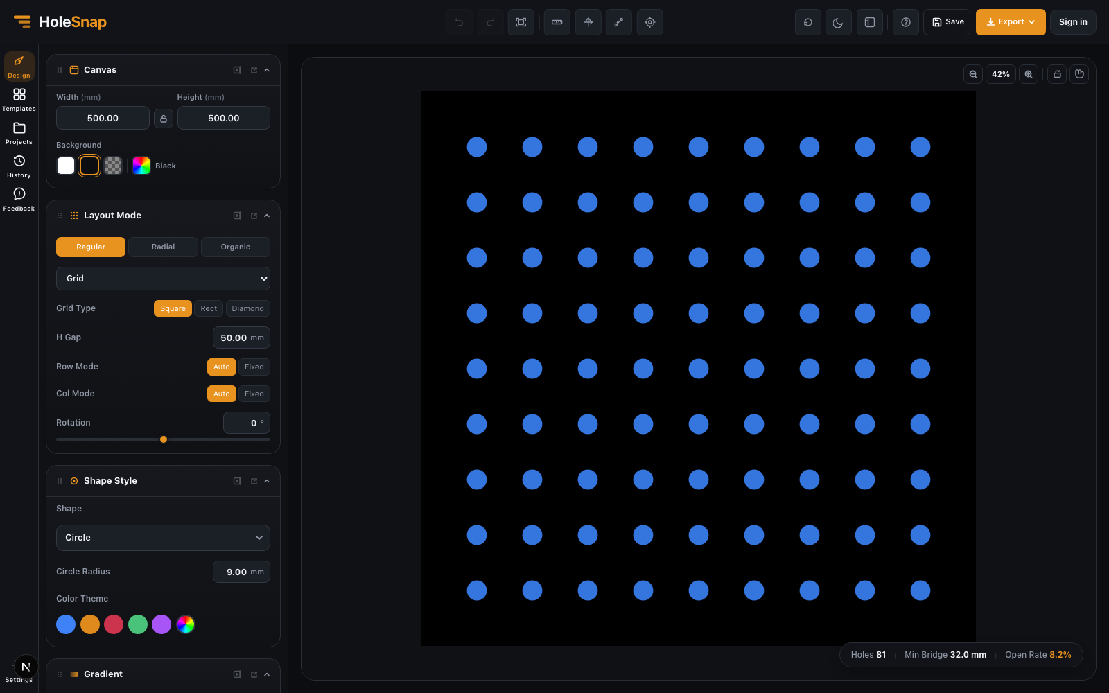
For example, a perforated panel preview may look like a simple dot grid, but the fabrication file needs real circular paths with units, spacing, and clean boundaries.
Common Controls in a Vector Pattern Generator
A practical vector pattern generator should let you control more than the visual style. The most important controls usually include:
- Canvas or panel size: the physical working area, usually in millimeters.
- Shape: Circle, Rectangle, Polygon, Diamond, Star, Ring, or Custom geometry. A rounded Rectangle can be used for a slot, while a six-sided Polygon creates a hexagon.
- Spacing or pitch: the distance between repeated elements.
- Density: how many shapes appear within the panel.
- Angle and rotation: how the pattern or individual shapes are oriented.
- Open area: how much of the panel is removed.
- Bridge width: how much material remains between openings.
- Boundary behavior: whether shapes are hidden, trimmed, or constrained inside an outline.
- Export format: SVG, DXF, or STP depending on the next tool.
These controls are connected. Increasing hole size can raise open area but reduce bridge width. Reducing pitch can make the pattern denser but weaker. Rotating slots can change airflow direction and visual rhythm. A good generator helps you see these effects before exporting.
Layout Types: Grid, Staggered, Radial, and Polar
Pattern layout defines how repeated geometry is arranged.
A regular grid is the simplest layout. It is easy to inspect and useful for rectangular panels, enclosure vents, and straightforward laser-cut patterns.
Staggered and hex-style layouts can create a denser visual field and may improve airflow or coverage. Honeycomb layouts are common in decorative panels and maker projects because they look structured and technical.
Radial and polar layouts are useful when the product is circular. Fan grills, speaker grilles, round vents, medallions, and circular inserts often need rings, sectors, or tangential shapes rather than rows and columns. HoleSnap’s Polar Array layout is a Plus feature.
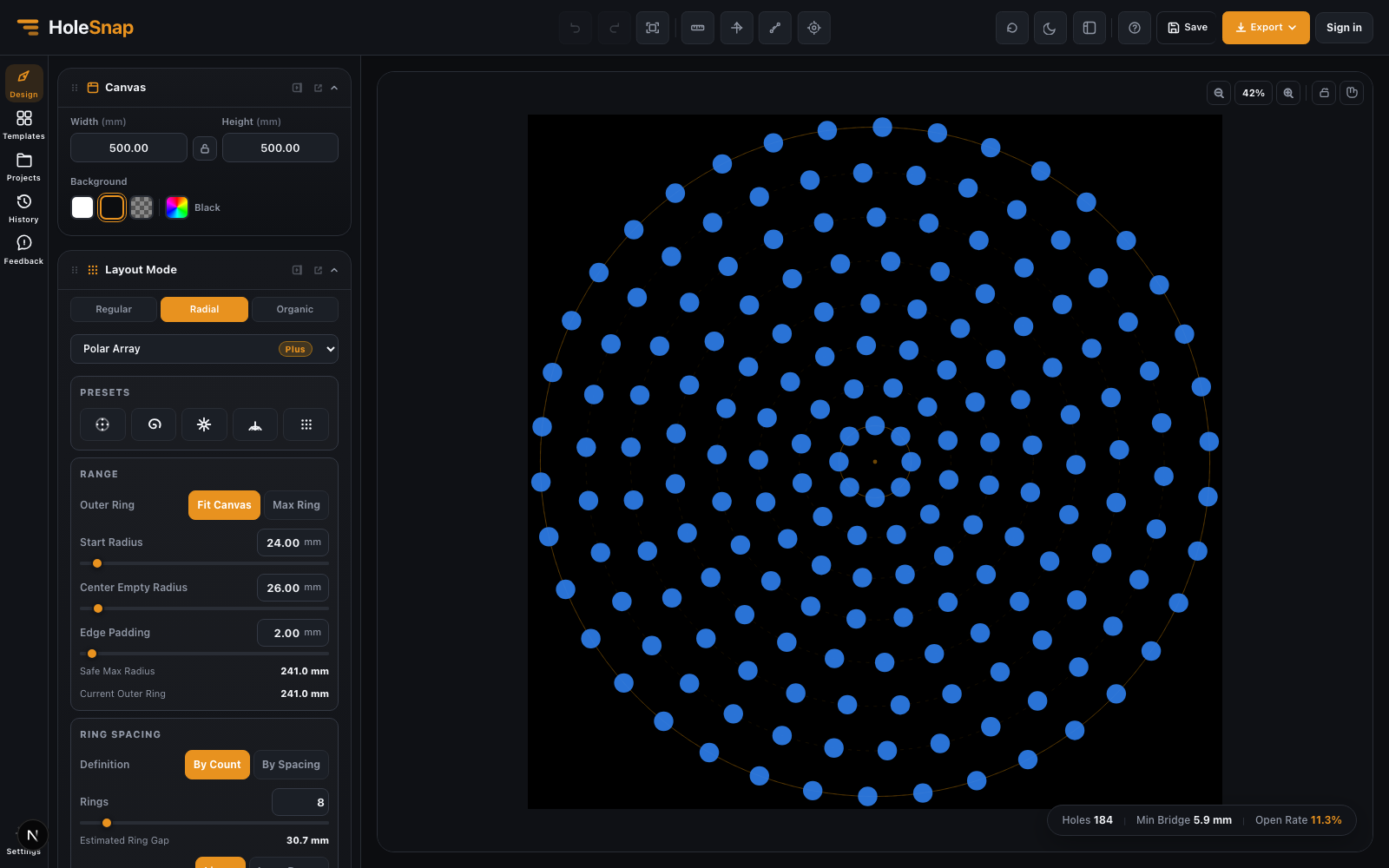
This is where a browser-based vector pattern generator can save time. Instead of building a circular array manually in CAD, you can control ring count, center clearance, point distribution, angle range, and orientation directly in the editor.
SVG, DXF, and STP: Which Export Should You Use?
Different workflows need different vector formats.
SVG is useful for lightweight vector editing, documentation, web preview, Figma, Illustrator, Inkscape, and design handoff. It is also useful when the pattern needs further graphic editing.
DXF is common in fabrication workflows. Laser cutting services, CNC operators, sheet metal shops, and CAD/CAM tools often expect DXF because it maps more directly to cut paths and machine-readable vector geometry.
STP is useful when the pattern needs to move into 3D CAD or product development workflows. If the perforated panel is part of a larger mechanical assembly, STP can be easier to review downstream.
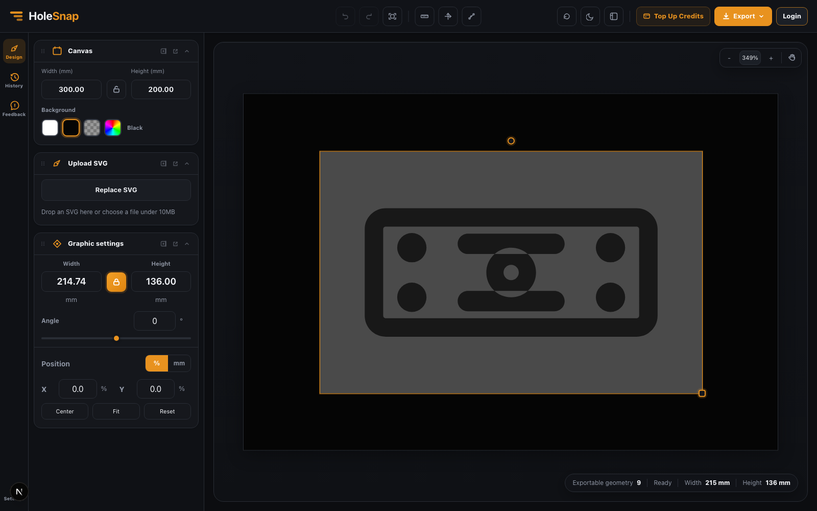
Before exporting, decide what the next tool needs. A designer may need SVG. A laser cutting workflow may need DXF. A mechanical product team may need STP.
What to Check Before Fabrication
A vector pattern that looks good on screen still needs manufacturing checks.
Before sending a file to laser cutting, CNC, or panel fabrication, review:
- Scale and units
- Closed paths
- Duplicate lines
- Minimum spacing
- Bridge width
- Edge margin
- Open area
- Material thickness
- Tool diameter or kerf
- Boundary cleanup
These checks matter because fabrication constraints are physical. If holes are too close, the material can weaken. If bridges are too narrow, they can warp, break, or burn through. If the file has duplicate lines, a laser cutter may cut the same path twice.
When to Use a Vector Pattern Generator
Use a vector pattern generator when the design is controlled by repeatable rules. It is especially helpful when you need to test several variations quickly.
Good use cases include:
- Comparing open area values
- Testing hole size and spacing
- Creating fan grill or speaker grille layouts
- Generating decorative perforated panels
- Creating SVG or DXF files without drawing every element manually
- Preparing vector geometry for CAD/CAM review
- Exploring pattern density before committing to CAD
It is not a replacement for final engineering review. For real production, exported files should still be checked in CAD/CAM software. But it can remove a large amount of repetitive drafting and make early design exploration much faster.
Final Thoughts
A vector pattern generator is useful because it connects visual design with editable geometry. You can explore patterns quickly, control values that affect the design, and export SVG, DXF, or STP files for CAD/CAM review and the next step in your workflow.
HoleSnap focuses on this practical middle ground: fast browser-based pattern creation, real design parameters, live preview, and vector export for design and fabrication workflows.