How to Create a Perforated Panel DXF Online
Creating a perforated panel DXF file used to mean opening traditional CAD software, drawing a panel outline, creating one hole, duplicating it across a grid, trimming the edges, and then checking the file for scale and spacing problems. For simple patterns this is repetitive. For dense perforated sheets, ventilation panels, speaker grilles, decorative screens, and sheet metal prototypes, it can become slow and error-prone.
An online perforated panel DXF generator makes the workflow much faster. Instead of drawing every hole manually, you define the panel size, choose the hole shape, set the spacing, check the open area and bridge width, then export a DXF file for your downstream workflow.
When an Online DXF Generator Helps
Online DXF generation is useful when the design is mostly pattern-based. Common examples include:
- Laser-cut ventilation panels
- CNC-routed grille plates
- Sheet metal prototypes
- Electronics enclosure vents
- Speaker or fan covers
- Decorative metal screens
- Product mockups that need a repeatable hole field
If your panel contains hundreds or thousands of repeated holes, an online generator can remove a large amount of manual CAD work. You still need to verify the exported file in CAD/CAM software before production, but the pattern creation stage becomes much more direct.
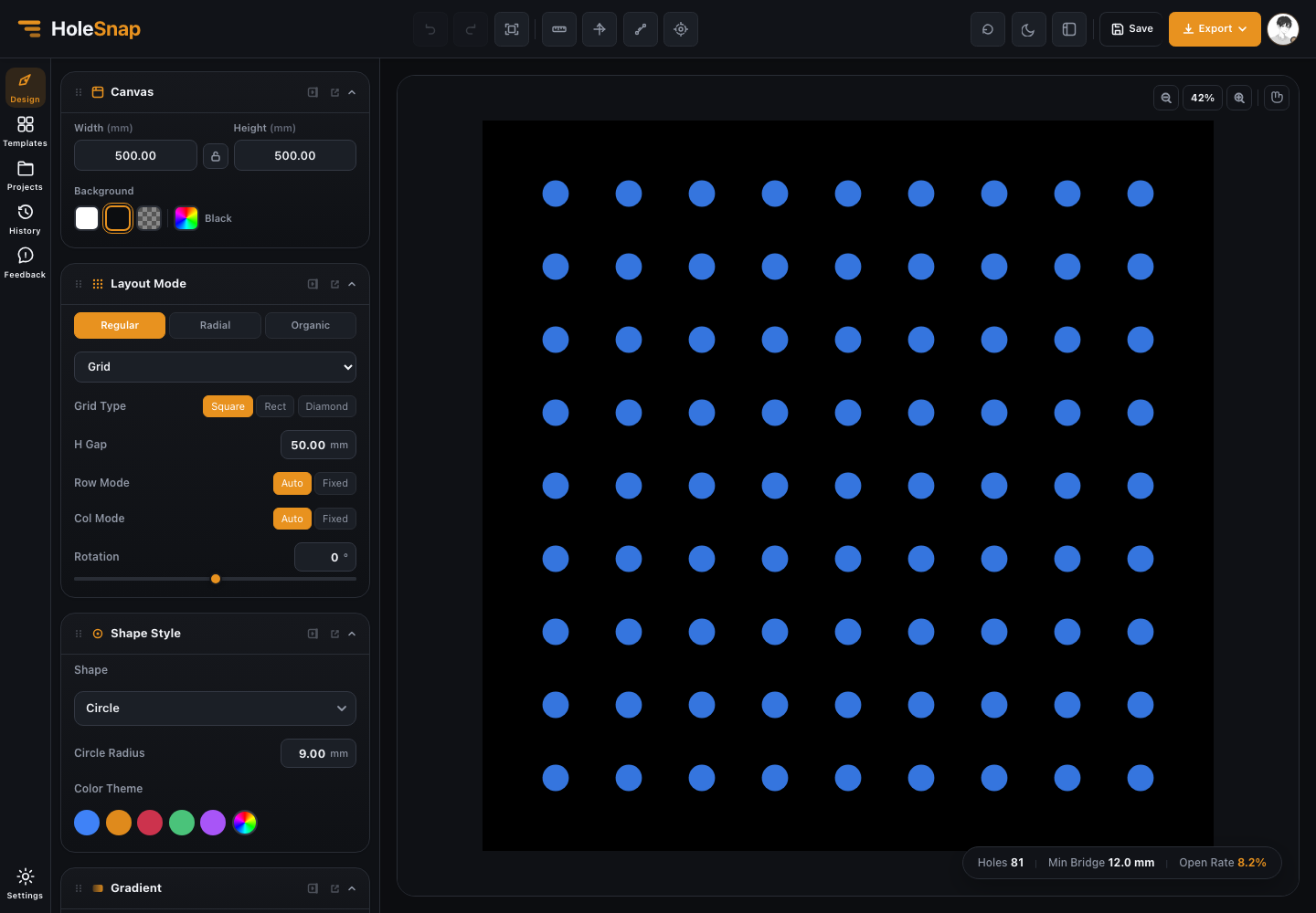
Step 1: Set the Panel Size
Start by entering the panel width and height. In most fabrication workflows, this is the physical size of the sheet or cut area, usually measured in millimeters.
For example, a small enclosure vent might use a 120 mm by 80 mm panel. A decorative screen might use a much larger rectangular area. The panel size matters because it controls how many holes fit, how the edge spacing behaves, and how the final DXF is scaled.
Use a simple rectangular panel for your first export. Once the base workflow is clear, you can add boundaries, rounded corners, or custom outlines.
Step 2: Choose a Hole Shape
The hole shape affects both the appearance and manufacturability of the panel.
Round holes are the safest starting point. They are common in perforated sheet design and easy to inspect. Rectangular holes and slots can create directional airflow or a grille-like look. Hexagons, diamonds, stars, rings, and custom shapes are more decorative and may need extra checks before fabrication.
Before exporting, confirm that your hole shape is compatible with your cutting process. Very sharp corners, tiny details, and narrow bridges can create problems in laser cutting, CNC routing, punching, or waterjet cutting.
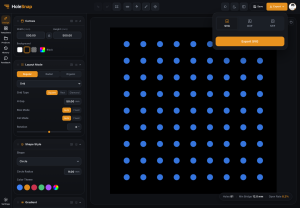
Step 3: Adjust Spacing and Pattern Layout
After choosing the hole shape, set the layout. A basic grid is easy to understand and inspect. Staggered and hex-style patterns often look denser and can improve airflow or visual coverage. More advanced layouts such as radial, spiral, random, or boundary-following patterns are useful for decorative or product-specific designs.
Spacing is one of the most important values in the file. If the spacing is too small, holes can overlap or leave bridges that are too weak. If spacing is too large, the panel may not provide enough airflow, light transmission, or visual density.
Step 4: Check Open Area and Bridge Width
Before exporting DXF, check the live metrics:
- Hole count
- Open area
- Minimum bridge width
Open area tells you how much of the panel is cut away. Higher open area can improve airflow and reduce weight, but it also removes more material. Minimum bridge width tells you how much material remains between neighboring holes. This matters for strength, heat distortion, and fabrication reliability.
A good DXF file is not just visually attractive. It also needs enough material left between holes and around edges.
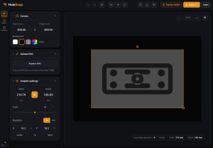
Step 5: Add a Boundary if Needed
For a rectangular sheet, you may not need a special boundary. But many real panels need holes to stay inside a specific region.
Use a boundary when:
- The panel is circular.
- The perforated area has rounded corners.
- Holes should avoid screw holes or mounting regions.
- The pattern should follow a custom imported outline.
- You only want complete holes inside the usable area.
Hide mode is useful when you want to remove holes outside a boundary. Trim mode is useful when the boundary should cut through partial holes at the edge.
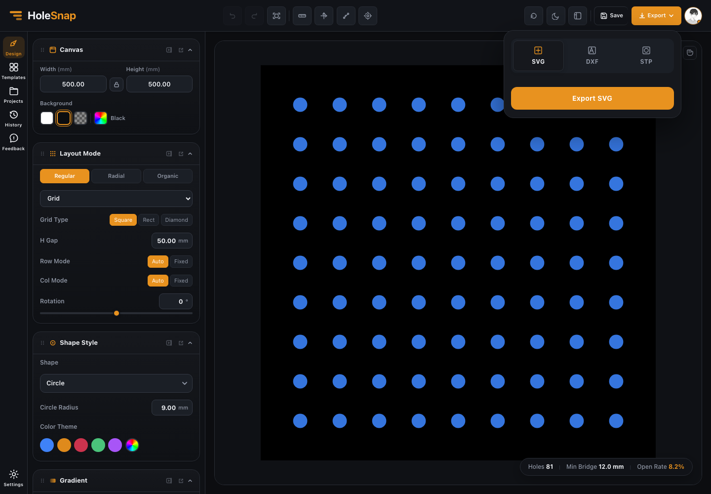
Step 6: Export DXF
When the pattern looks right, open the export panel and choose DXF.
Before sending the file to fabrication, open it in your CAD/CAM software and check:
- Units and scale
- Board outline
- Hole geometry
- Edge trimming
- Duplicate or overlapping lines
- Minimum spacing
- Toolpath compatibility
The online generator gets you to a clean starting file quickly. Final production approval should still happen in the same software or process your fabricator uses.
Final Thoughts
Creating a perforated panel DXF online is a practical way to speed up repetitive CAD work. It is especially helpful for makers, fabricators, product designers, and engineers who need to test different hole sizes, layouts, open areas, and bridge widths before exporting a fabrication file.
Start simple: set the panel size, choose round holes, use a regular layout, check open area and bridge width, then export DXF. Once the first file is working, you can explore custom boundaries, gradients, and more expressive patterns.