Gradient Control Points and Lines #
Overview #
Gradient controls define where a variation starts, how far it spreads, and how it fades across the panel. HoleSnap supports two main control types: Control Points and Gradient Lines.
Control points are best for radial or local effects. Gradient lines are best for directional fades and banded effects.
Control Points #
A control point creates a circular influence zone around a location on the panel.
Use control points when you want:
- Larger holes around a feature area.
- A radial fade from the center.
- A local density or shape change.
- A cluster effect near a corner or focal point.
Each control point has:
- Position: X/Y location on the panel.
- Influence Radius: how far the effect spreads.
- Mapping Mode: Clamp, Repeat, or Mirror.
- Dimension settings: size, rotation, shape, or density behavior.
- Enable toggle: temporarily turn the point on or off.
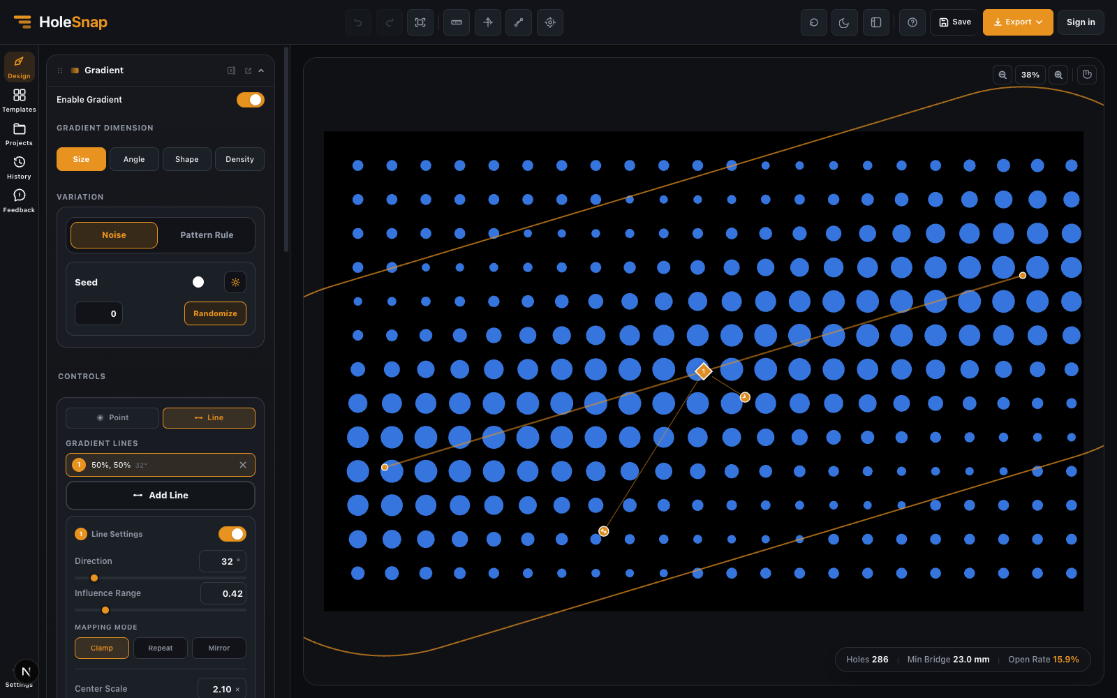
Gradient Lines #
A gradient line creates a band or directional field across the panel.
Use gradient lines when you want:
- A left-to-right size fade.
- A top-to-bottom airflow zone.
- A diagonal transition.
- A stripe-like repeated gradient.
- A controlled design direction.
Each gradient line has:
- Position: where the line sits on the canvas.
- Direction: line angle.
- Influence Range: how wide the gradient band is.
- Mapping Mode: Clamp, Repeat, or Mirror.
- Dimension settings: size, rotation, shape, or density behavior.
- Enable toggle: temporarily turn the line on or off.
Multi-Line Controls #
Multi-line controls let you draw a line with multiple points. This is useful when a gradient needs to follow a bend, corner, or custom path instead of a single straight direction.
Use a multi-line control for:
- Curved or angled decorative transitions.
- Gradient bands that follow a design feature.
- Local effects near an irregular boundary.
When drawing a multi-line:
- Choose the line tool.
- Left-click to start the line.
- Left-click again to add more corners.
- Right-click or press Enter to finish.
Choosing Point vs Line #
Use this rule:
- Choose Point when the effect has a center.
- Choose Line when the effect has a direction.
- Choose Multi-Line when the effect follows a path.
For example, a circular highlight on a speaker grille should use a point. A fade across a cabinet panel should use a line. A decorative band following a curved edge should use a multi-line.
Mapping Modes #
Clamp applies the effect once inside the influence area.
Repeat repeats the effect in regular intervals.
Mirror repeats the effect while alternating direction.
For production files, start with Clamp. Repeat and Mirror are powerful, but they can create more complex patterns and should be checked carefully before export.
Coordinate Modes #
Gradient controls can be positioned by percentage or by millimeters.
Use percentage when you are quickly placing controls visually.
Use millimeters when the gradient must align with a real feature, such as a fan opening, mounting area, or product edge.
Good Workflow #
- Enable one gradient dimension.
- Add one point or line.
- Adjust influence range.
- Check the preview.
- Add a second control only if needed.
- Disable controls temporarily when comparing versions.
This keeps the design predictable and makes problems easier to find.
What to Check #
Before exporting, inspect:
- The largest holes.
- The smallest holes.
- Minimum bridge width.
- Holes near the boundary.
- Open area in dense zones.
- Whether repeated or mirrored effects create unexpected bands.


